Microstrip isolator
6SO-112
6SO-112
Technical conditions
The electromagnetic parameters of the ferrite microstrip decoupler at acceptance and delivery under normal environmental conditions must conform to table:
| Frequency, GHz | Insertion losses, dB | Inverse losses, dB | VSWR | Temperature, °C | Max input power, W | ||||
|---|---|---|---|---|---|---|---|---|---|
| min | max | min | max | min | max | min | max | ||
| 3.90 | 4.60 | 0.40 | 0.50 | 20 | 30 | 1.30 | -60 | 85 | 2 |
- Devices able to operate in the the working temperature range .
- Reflected continuous power absorbed by the load is not more than 2 watt .
- Direct losses given relative to polycarbonate microstrip line with a characteristic impedance 50 ohms in open space.
- Geometry and dimensions of mounting camera is not defined .
- Device soldering temperature should not exceed the 150°C.
- Peak temperature on the adhesive seams should not exceed the 180°C.
- Matching transformers are optimized for microstrip line with permittivity ε=9.8.
- Optionally, optimization can be made on a coaxial transitions of the customer or microstrip line with lower permittivity.
If you have technical or commercial questions, contact us by email

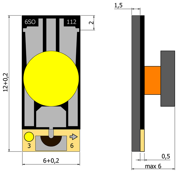
Figure 1. Overall and mounting dimensions.
|
6SO-112
|
 |
6SO-112-1
|
 |
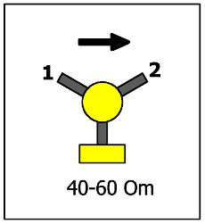
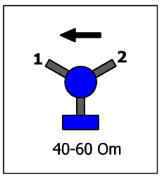
Figure 2. Design versions.
- *The actual price depends on the number of products and may differ from that given on the site.